INTRODUCTION
Variable thermal conductance is achieved in a heat pipe
by controlling liquid or vapor flow. Figure 1 is a review
of the various concepts proposed to vary thermal conductance
in heat pipes. Figure lA shows the concept of tilt control(l).
By tilting the heat pipe in a l-G environment, liquid will
move from one end to the other. As shown in Figure lA, heat
enters the evaporator, -vaporizes liquid and vapor is driven
to the condenser. Normal heat pipe action commences. How-
ever, if the heat pipe is tilted in the other direction,
liquid flows to the condenser and if there is not sufficient
capillary action to bring the liquid back to the evaporator,
heat pipe action stops. Tilting angles between the on and
off angles result in a modulation of thermal conductance.
Figure lB shows the condenser blockage technique. A noncondensible
gas is placed in the heat pipe and during heat
pipe operation this gas is driven to the condenser. Variable
conductance is achieved when this gas front expands or con-
tracts, utilizing either heat or bellows, to block the con-
denser. Evaporating vapor will not penetrate the gas front
and therefore, heat rejection area is limited and thermal
conductance decreases.
Figure lC shows the vapor flow control device using a
valve. This heat pipe is configured for holding evaporator
temperature at a constant value. As the heat in the
evaporator increases, the bimetallic spring opens the
valve and vapor flows through the valve to the condenser.
As the evaporator cools, the bimetallic spring changes
the valve setting and modulates the vapor to hold the
constant temperature.
Another liquid flow control device utilizing an active
pumping means is shown in Figure ID. Here liquid is
pumped into the evaporator utilizing a bubble pump. The
bubble pump can move large amounts of liquid and result
in a wide range of thermal conductances. Power requirements
for this device are on the order of 1% of the power
transmitted by the heat pipe.
Figure IE shows a liquid flow control device utilizing
rotation. With the heat pipe in the position as shown,
liquid is trapped in a U-tube. If the device is rotated
900 so that the U is not visible while viewing along the
horizontal plane, liquid flows to the evaporator and heat
pipe operation commences. Heat flow modulation in this
device is achieved by various angles of rotation.
Figure IF is the heat pipe design that is the subject of
this paper. By bending the body of the heat pipe, liquid
is trapped. Variable bends result in various amounts of
liquid available to the evaporator. This paper presents
data, analysis and application concerning this deformable
heat pipe.
DEFORMABLE BODY HEAT PIPE CONCEPT
Figure 2 depicts the concept of the variable conductance
operation of the deformable body heat pipe. Figure 2A
shows the heat pipe in the high rate of heat transfer
operating mode. All liquid is in the evaporator being
evaporated as or in the stage of drain back from the
condenser. Multiple wicks are all wetted inside the
evaporator. Figure 2B shows the modulating mode. By
deforming the body at the location designated, a given
amount of liquid is trapped in a reservoir. The reservoir
is not sufficient to entrap all liquid, so some
liquid does arrive at the evaporator. It should be
noticed that the liquid reservoir now in the evaporator
is lower and that some wicks are exposed and desaturated.
This results in less liquid available in the evaporator
and a more concentrated evaporating area. The result is
more thermal constriction and loss of heat transfer
rate. As we go to Figure 2C we see the deformable body
device in the off position. The deformation is large
enough such that all returning liquid is entrapped and
no liquid is available for the evaporation. This is the
off mode.
TEST APPARATUS
In order to gage the performance of the deformable body
heat pipe, a test apparatus was constructed. Figure 3
shows the test apparatus in operation. The heat pipe
length was approximately four feet. The tubing diameter
is 3/8 inch in outside diameter. The body material was
copper. The deformable section is made of flexible,
stainless steel tubing. This was coupled to the heat
pipe by typical pipe fittings. Normally, the body material
would be welded into the heat pipe itself. Figure
3A is an overall view of the apparatus. As shown in
Figure 3B the body can be deformed by a thumb screw
moving the deformable portion of the heat pipe up and
down. Various heat transfer rates are obtained by how
much the thumb screw is turned to deform the heat pipe.
Figure 3C shows the heat pipe in the on mode. A small
nichrome wire wrap heater was placed at one end and
thermocouples were mounted in the evaporator to determine
temperature rise in the evaporator and gage the operation
of the device. Methanol was used as the working fluid.
Tests were run at various power levels and various periods
of time. Thermal conductance was altered simply by turning
the thumb screw.
EXPERIMENTAL RESULTS
For a test period of approximately five hours, data was
recorded on evaporator temperatures and heat transfer
rates of the system.
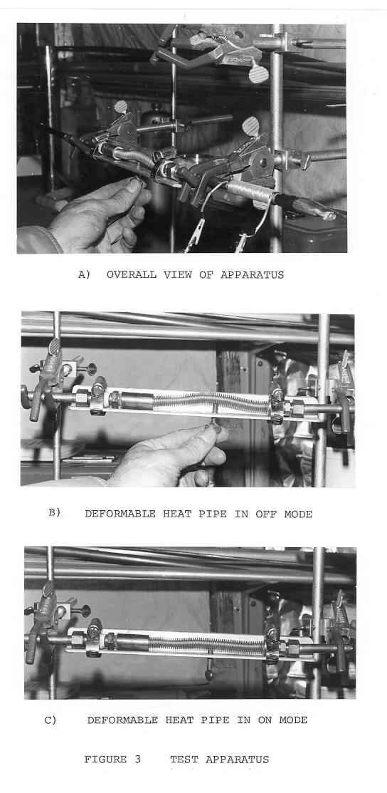
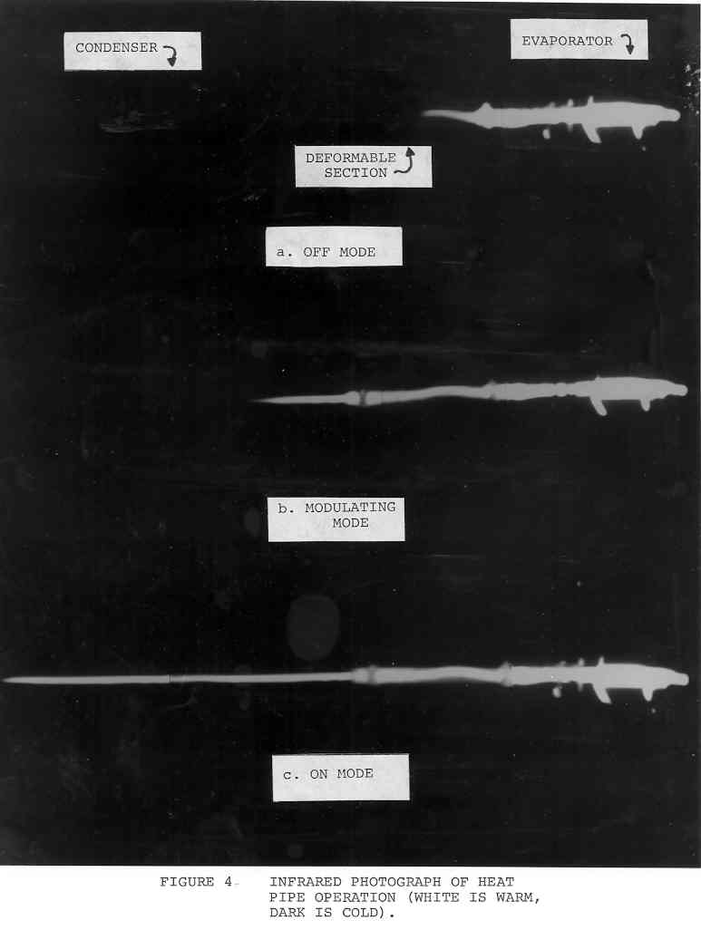
Figure 4 is an infrared photograph of the operation of
the heat pipe. High temperatures are depicted as light
areas. Figure 4A shows the heat pipe in the off mode.
No vapor has penetrated beyond the deformable section.
In Figure 4B the bend in the heat pipe is reduced and a
small amount of liquid is released to the evaporator,
resulting in vapor penetration into the condenser. This
is the modulatory mode. Figure 4C is the full on mode and
all liquid is available to the evaporator.
Shown in Figure 5 are the results of this test. Early in
the test phase the heat pipe was allowed to operate at full
power, which was approximately 15.3 watts. Early into the
test, at approximately 15 minutes, the heat pipe was turned
off quickly and then turned on again. You could see the
thermal spike going up to approximately 80 C. During this
transient the heat pipe was turned on again totally and we
could see the temperature and wattage coming back to approximately
the same level, demonstrating the repeatability of
this device. During the next test the heat pipe was turned
off entirely and the temperature was allowed to rise
until it stabilized, as shown at the zero watt reading.
After five to six minutes of this mode the thumb screw
was backed off to come to an intermediate heat transfer
rate. This turned out to be approximately 7.8 watts.
That temperature was held for a period of time and then
the heat pipe was turned off again. Again the temperature
rose until the zero watt reading was maintained.
The repeatability appeared to be very good, considering
the simplicity of the apparatus.
Throughout the testing and flexing of the heat pipe, the
deformable portion always came back to center. There was
no apparent evidence of plastic deformation or fatigue.
APPLICATIONS
An application of this device in the solar energy area is
depicted in Figure 6. A heat pipe solar collector transfers
heat passively into a solar storage device. Heat is
stored in this device for immediate usage or for storage
for non-solar hours. The deformable body heat pipe is
placed in the storage device and conducts heat to the
using area. The deformable body is controlled by a thermo-
statically actuated plunger. This plunger senses the environmental
conditions inside of the using area and adjusts
the deformable body heat pipe accordingly. The deformable
body heat pipe is sensitive to tilting angles. Therefore,
its best utilization is in a stationary environment, such
as this solar heating system. Once installed, the plunger
can be easily calibrated to the proper temperature by simply
adjusting the plunger with respect to the bimetallic strip.
As the air temperature inside the home increases, the bimetallic
strip changes position, pointing to the 22C position.
This results in a shut off of a significant amount
of heat going to the house because the deformable body heat
pipe is trapping liquid in the trap reservoir. As the
temperature inside goes down, more liquid is released to
the heat pipe and heat transfer increases. This is a simple
feed back mechanism that requires no energy to operate.
It is interesting that coupling a heat pipe solar
collector and the deformable body heat pipe can achieve
a very nearly passive system. No external energy is
required for operating control systems.
CONCLUSIONS
The performance of the deformable body variable conductance
heat pipe has been demonstrated through a simple
experimental apparatus. The device has potential in
stationary systems, where passive variable conductance
over wide temperature ranges are required. Coupling this
device to a storage unit that is supplied by a heat pipe
solar collector, one can achieve a very nearly passive
solar heating system. Data shows the heat pipe to vary
thermal conductance over a wide range of wattage with
relatively little leakage in the off mode.
REFERENCES
1. Q-Dot Corporation, 151 Regal Row, Suite
120, Dallas, Texas
.
2. Heat Pipe Design Handbook, DRDN. SE-345T.
3. Roberts, Charles C., "A Variable Conductance
Heat Pipe Using Bubble Pump Injection", 2nd
International Heat Pipe Conference, Bologna,
Italy.
BACK TO C. ROBERTS CONSULTING ENGINEERS HOME PAGE,
WWW.CROBERTS.COM
DEFORMABLE BODY HEAT PIPE CONCEPT
Figure 2 depicts the concept of the variable conductance operation of the deformable body heat pipe. Figure 2A shows the heat pipe in the high rate of heat transfer operating mode. All liquid is in the evaporator being evaporated as or in the stage of drain back from the condenser. Multiple wicks are all wetted inside the evaporator. Figure 2B shows the modulating mode. By deforming the body at the location designated, a given amount of liquid is trapped in a reservoir. The reservoir is not sufficient to entrap all liquid, so some liquid does arrive at the evaporator. It should be noticed that the liquid reservoir now in the evaporator is lower and that some wicks are exposed and desaturated. This results in less liquid available in the evaporator and a more concentrated evaporating area. The result is more thermal constriction and loss of heat transfer rate. As we go to Figure 2C we see the deformable body device in the off position. The deformation is large enough such that all returning liquid is entrapped and no liquid is available for the evaporation. This is the off mode.
TEST APPARATUS
In order to gage the performance of the deformable body heat pipe, a test apparatus was constructed. Figure 3 shows the test apparatus in operation. The heat pipe length was approximately four feet. The tubing diameter
is 3/8 inch in outside diameter. The body material was
copper. The deformable section is made of flexible,
stainless steel tubing. This was coupled to the heat
pipe by typical pipe fittings. Normally, the body material
would be welded into the heat pipe itself. Figure
3A is an overall view of the apparatus. As shown in
Figure 3B the body can be deformed by a thumb screw
moving the deformable portion of the heat pipe up and
down. Various heat transfer rates are obtained by how
much the thumb screw is turned to deform the heat pipe.
Figure 3C shows the heat pipe in the on mode. A small
nichrome wire wrap heater was placed at one end and
thermocouples were mounted in the evaporator to determine
temperature rise in the evaporator and gage the operation
of the device. Methanol was used as the working fluid.
Tests were run at various power levels and various periods
of time. Thermal conductance was altered simply by turning
the thumb screw.
EXPERIMENTAL RESULTS
For a test period of approximately five hours, data was
recorded on evaporator temperatures and heat transfer
rates of the system.
Figure 4 is an infrared photograph of the operation of
the heat pipe. High temperatures are depicted as light
areas. Figure 4A shows the heat pipe in the off mode.
No vapor has penetrated beyond the deformable section.
In Figure 4B the bend in the heat pipe is reduced and a
small amount of liquid is released to the evaporator,
resulting in vapor penetration into the condenser. This
is the modulatory mode. Figure 4C is the full on mode and
all liquid is available to the evaporator.
Shown in Figure 5 are the results of this test. Early in
the test phase the heat pipe was allowed to operate at full
power, which was approximately 15.3 watts. Early into the
test, at approximately 15 minutes, the heat pipe was turned
off quickly and then turned on again. You could see the
thermal spike going up to approximately 80 C. During this
transient the heat pipe was turned on again totally and we
could see the temperature and wattage coming back to approximately
the same level, demonstrating the repeatability of
this device. During the next test the heat pipe was turned
off entirely and the temperature was allowed to rise
until it stabilized, as shown at the zero watt reading.
After five to six minutes of this mode the thumb screw
was backed off to come to an intermediate heat transfer
rate. This turned out to be approximately 7.8 watts.
That temperature was held for a period of time and then
the heat pipe was turned off again. Again the temperature
rose until the zero watt reading was maintained.
The repeatability appeared to be very good, considering
the simplicity of the apparatus.
Throughout the testing and flexing of the heat pipe, the
deformable portion always came back to center. There was
no apparent evidence of plastic deformation or fatigue.
APPLICATIONS
An application of this device in the solar energy area is
depicted in Figure 6. A heat pipe solar collector transfers
heat passively into a solar storage device. Heat is
stored in this device for immediate usage or for storage
for non-solar hours. The deformable body heat pipe is
placed in the storage device and conducts heat to the
using area. The deformable body is controlled by a thermo-
statically actuated plunger. This plunger senses the environmental
conditions inside of the using area and adjusts
the deformable body heat pipe accordingly. The deformable
body heat pipe is sensitive to tilting angles. Therefore,
its best utilization is in a stationary environment, such
as this solar heating system. Once installed, the plunger
can be easily calibrated to the proper temperature by simply
adjusting the plunger with respect to the bimetallic strip.
As the air temperature inside the home increases, the bimetallic
strip changes position, pointing to the 22C position.
This results in a shut off of a significant amount
of heat going to the house because the deformable body heat
pipe is trapping liquid in the trap reservoir. As the
temperature inside goes down, more liquid is released to
the heat pipe and heat transfer increases. This is a simple
feed back mechanism that requires no energy to operate.
It is interesting that coupling a heat pipe solar
collector and the deformable body heat pipe can achieve
a very nearly passive system. No external energy is
required for operating control systems.
CONCLUSIONS
The performance of the deformable body variable conductance
heat pipe has been demonstrated through a simple
experimental apparatus. The device has potential in
stationary systems, where passive variable conductance
over wide temperature ranges are required. Coupling this
device to a storage unit that is supplied by a heat pipe
solar collector, one can achieve a very nearly passive
solar heating system. Data shows the heat pipe to vary
thermal conductance over a wide range of wattage with
relatively little leakage in the off mode.
REFERENCES
1. Q-Dot Corporation, 151 Regal Row, Suite
120, Dallas, Texas
.
2. Heat Pipe Design Handbook, DRDN. SE-345T.
3. Roberts, Charles C., "A Variable Conductance
Heat Pipe Using Bubble Pump Injection", 2nd
International Heat Pipe Conference, Bologna,
Italy.
BACK TO C. ROBERTS CONSULTING ENGINEERS HOME PAGE,
WWW.CROBERTS.COM
CONCLUSIONS
The performance of the deformable body variable conductance heat pipe has been demonstrated through a simple experimental apparatus. The device has potential in stationary systems, where passive variable conductance over wide temperature ranges are required. Coupling this device to a storage unit that is supplied by a heat pipe solar collector, one can achieve a very nearly passive solar heating system. Data shows the heat pipe to vary thermal conductance over a wide range of wattage with relatively little leakage in the off mode.
REFERENCES
1. Q-Dot Corporation, 151 Regal Row, Suite 120, Dallas, Texas
. 2. Heat Pipe Design Handbook, DRDN. SE-345T.
3. Roberts, Charles C., "A Variable Conductance Heat Pipe Using Bubble Pump Injection", 2nd International Heat Pipe Conference, Bologna, Italy.
BACK TO C. ROBERTS CONSULTING ENGINEERS HOME PAGE,
WWW.CROBERTS.COM
WWW.CROBERTS.COM