Roof failures are at the heart of many insurance claims. Improper design, deterioration, overloading, inadequate repair, and weather related influences are known contributors to the failure of a roof structure. Before launching into our case studies, perhaps a refresher on roof structures is in order. Figure 1 shows
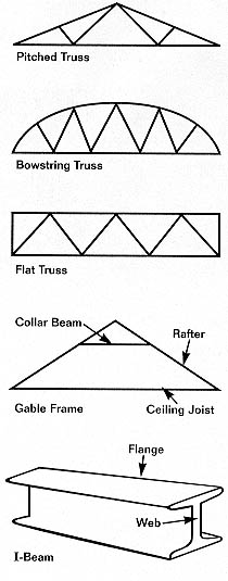
Figure 1
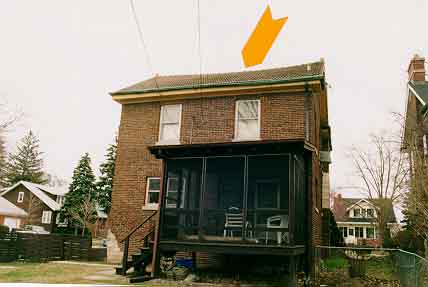
Figure 2
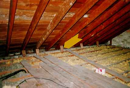
Figure 3
Figure 2 is an example of ridge sag on 60 year old brick home. Figure 3 is a view inside the attic showing the rafters and the absence of collar beams and joist connections to the rafters. Since the attic floor joists are parallel to the ridge board, there was no structural benefit to the roof framing. The rafters were nailed to small wood supports that engaged the masonry wall to prevent the rafters from moving laterally with respect to the ridge. Over time, these supports had failed, causing rafters to move laterally and resulting in the ridge settling in the shape shown in Figure 2. This is an example of non-standard framing, characteristic of old buildings, that is structurally deficient for the long term.
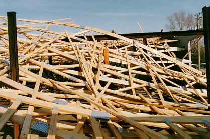
Figure 4
Figure 4 shows a catastrophic collapse of partially constructed pitched roof trusses. Winds of approximately 50 MPH caused the collapse. Investigation of the remains showed relatively few braces and in many places a single nail joining many structural members. Structural elements under construction are vulnerable to wind conditions since the full structure required to resist wind loading has not been installed. Consequently, good construction techniques dictate proper temporary bracing of the structure which was lacking in this case.
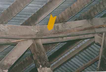
Figure 5
Figure 5 shows a cracked member in a wood truss in a large metal pole building. The truss cracked during unloading of grain from the building. Figure 6 shows grain deposits adhering to the bottom cord. Apparently, the grain level was
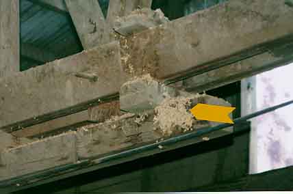
Figure 6
nearly at the roof and above the truss system since it is loaded by an auger at the ridge. The grain was in the bin several months before withdrawal, allowing consolidation and adhesion to the roof trusses. When the grain was removed from below, the weight of the grain that adhered to the structure overloaded the old trusses, causing failure. This is a common problem with grain storage structures because of the unpredictable nature of compacted grain when unloading.
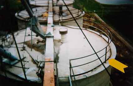
Figure 7
Figure 7 is a view of a large grain bin where the concrete roof began to deflect downward. Figure 8 shows an I-beam, which was a major support for the roof, also deflecting downward. Beam connection had corroded over time and allowed the beam end to slip out of position. This is an example of corrosion taking its toll over a 40 year period.
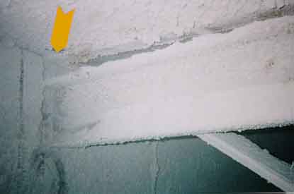
Figure 8
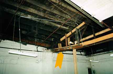
Figure 9
Figure 9 is a view of a bow truss that had been reinforced using wood and steel. The temporary column used to support the structure was not supporting the piece of steel used in the repair. Consequently the steel that had been added to the structure, performed no useful purpose but added to the load on the truss. This is an example of a "handy man" repair performed by the building owner. These repairs, not usually inspected by governing authorities, are often inadequate and are a cause of roof failure. When investigating roof losses, information on environmental conditions at the time (wind, rain, etc) helps establish an initiating event to the collapse. In many instances, a moderate wind can cause the collapse of a marginal structure. Inspect the debris as soon as possible lest clean up efforts spoliate the evidence. (see Claims Magazine June 1992) When analyzing the cause of failure, finite element structural analysis computer programs are readily available to identify weakness in structural design (see Claims Magazine June 1987).
FOR TECHNICAL ARTICLES CONTACT CLAIMS MAGAZINE AND ASK
FOR A REPRINT OF A PAST TECHNICAL NOTEBOOK ARTICLE
CLAIMS MAGAZINE
BACK TO C. ROBERTS CONSULTING ENGINEERS HOME PAGE,
WWW.CROBERTS.COM
WWW.CROBERTS.COM